USBチャンネル切換器: ハードウェア編
設計
切換器の製作にあたって、まずはいろいろな可能性を検討したのだが、 その取捨選択は次のような明確な設計方針のもとに行われた。
- 12チャンネル程度は扱えること。
- 面倒な工作はしたくない。
- デバイスドライバをわざわざ書きたくない。
つまりは面倒な事は一切したくなかったのだ。当初はパラレルポートの使用等も検討したのだが、 ノートパソコンで扱うのに不便でもあり、何か良い方法はないかと考えるうちに、 USB接続のジョイパッドを利用する事を考えついた。
いまどきのジョイパッドにはボタンがやたらと沢山ついているから、 それらのスイッチ部分をそのままロータリースイッチにつなげば工作も簡単だし、 デバイスドライバも汎用のものをそのまま使える訳だ。という訳で、 さっそく電気屋に行って部品の物色を開始した。
使用した部品
| 品名 | 型番 | 値段(売価:円) |
|---|---|---|
| 1回路12接点ロータリースイッチ | SRN101C | 260 |
| 12ボタンUSBジョイパッド | JC-U812 | 1280 |
| シャーシ | TS-1 | 670 |
| ツマミ | --- | 160 |
ロータリースイッチは、御存知アルプス電気社製の12接点のものを選択。 ショーティングについては、ソフトウェア側で対応するという事で、とりあえず売場にあったものを購入した。

今回使用したジョイパッド。12ボタンあるので、入力は全てボタン入力として扱えるのが便利。今回使用しなかった十字キーの分も使えば、16チャンネルまでいける筈。
製作
製作といっても、ジョイパッドをバラして基板を取り出し、 ロータリースイッチを導線でつないで、シャーシに収めるだけの簡単工作。 おおざっぱな手順は以下の通り。
- USBジョイパッドをバラし、不要な部品(LRボタン)を切り取る。
- USBケーブルがついたコネクタを基板から外す。(要ハンダ吸い取り作業)
- 基板中央のICに、導線を13本ハンダづけする。
- 13本の導線をロータリースイッチにハンダづけする。
- シャーシに穴を開ける。(3箇所)
- 組み立てる。(USBケーブルを再度取り付ける)
- お好みで、レタリングシートを貼る。
まずは下図のように基板の裏の足に導線をつけていく。
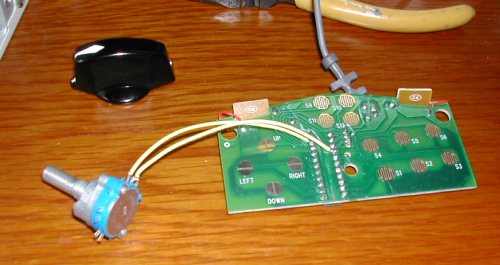
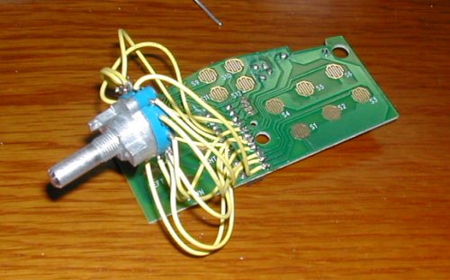
13本もあると、導線の取りまわしにかなり苦労する。
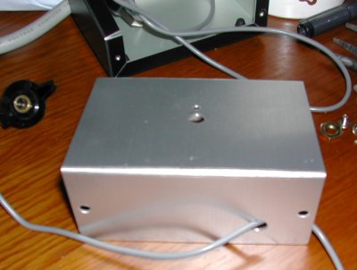
加工したシャーシ。ロータリースイッチ取り付け部には、 共回り防止の突起を入れるための穴が主軸用の穴の脇に開けてある。
スイッチと基板をこのように組み入れていく。
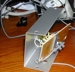
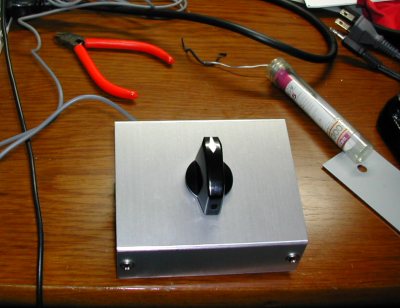
組み上がり。このままでもいい感じ。
レタリングシートで数字を転写。しかし、この方法だと耐久性が無いため、 ちょっと乱暴に扱うとすぐ数字が欠けてしまう。何らかのコーティングをするべき。
![[写真7]](gacha4.jpg)